
Language:

- All
- Product Management
- News
- Introduction
- Enterprise outlets
- FAQ
- Enterprise Video
- Enterprise Atlas

Product classification
Contact Us
Tel:+86-0755-27345677 +86-0755-27337559
Fax:+86-0755-81461216
Website: http://en.chinalcdclx.com
E-mail:chinalcdclx@126.com
Add:1-3/F, Building 9, Jinwen Wenwu Science and Technology Park, No. 50, Hebin South Road, Songgang Town, Bao'an District, Shenzhen, Guangdong, China
Technology Center
Driving Principle and Precautions of TN LCD
Release time:
2019-06-28
TN LCD screen adopts static driving mode. The static driving means that a driving voltage is continuously applied to the pixel electrode and the common electrode to be displayed at the same time until the display time ends. Since the driving voltage is always maintained during the display time, it is called static driving. The following takes the most commonly used pen-type TN liquid crystal display as an example for description.
The section type TN liquid crystal display screen is displayed by section-shaped display pixels. Segment-shaped display pixel means that the display pixel is a long bar shape, also known as a pen segment shape. In digital display, a seven-segment electrode structure is often used, that is, each digit consists of an "8"-shaped common electrode and seven segment-shaped electrodes that form an "8"-shaped pattern, which are arranged in two pieces.Substrateon, as shown in Figure 1.
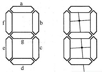
Fig. 1 Electrode arrangement diagram of seven-segment LCD screen
The driving voltage of each pen segment is AC 3~5V, and the frequencies are 32Hz, 167Hz and 200Hz. During operation, a continuous square wave with a duty ratio of 1/2 is continuously added to the back electrode (COM), and a continuous square wave with opposite phase, equal amplitude and same frequency as the voltage waveform on the back electrode is applied to the pen segment to be displayed, then a voltage of twice the square wave amplitude of positive and negative alternating is applied to the displayed pen segment, which should be greater than that of the liquid crystal display device.threshold voltage14h; However, if a waveform with the same phase, amplitude and frequency as the voltage waveform on the back electrode is applied to the pen segment that does not need to be displayed, an electric field cannot be formed on the pen segment, and of course, it cannot be displayed. Figure 2 shows a pen segment electrode LCD driverCircuitPrinciple and waveform diagram.
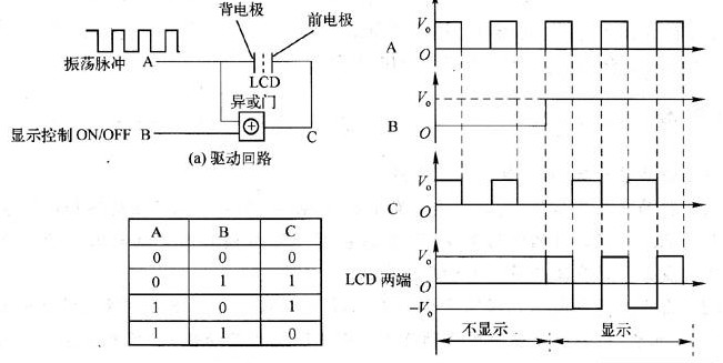
Fig.2 Principle and waveform of LCD driving circuit of a pen segment electrode
2(a) is an exclusive OR gate circuit. The input terminal A is a square wave oscillation pulse scoop generated by the oscillation circuit and is directly connected to the COM terminal of the liquid crystal display screen. The input terminal B can be connected to high and low (ON/OFF) levels for controlling the on and off of the electrodes. The output terminal C of the XOR gate is connected to the front electrode (terminal A, B, C, D, E, F or G) of the pen segment end of the liquid crystal display screen.
The AC driving waveforms at both ends of the liquid crystal display (LCD) can be obtained from the XOR gate truth table shown in Figure 2 (B), as shown in Figure 2(c). It can be seen that when the voltage phases of the two electrodes on the field are the same, the potential difference between the two electrodes is zero, and the field is not displayed; when the voltage phases of the two electrodes on the field are opposite, the potential difference between the two electrodes is a square wave voltage with twice the amplitude, and the field appears black.
LCD display driver andLEDThe drive is very different. In the case of an LED, a constant on or off voltage is applied to both ends of the LED to control its light or dark. The LCD, because of its two poles can not add a constant DC voltage, which brings complexity to the drive. Generally, a constant alternating square wave signal should be added to the common pole (usually the back pole) of the LCD, and the required zero voltage or twice the amplitude of the alternating voltage should be generated between the two poles of the LCD by controlling the voltage change of the front pole. To achieve the control of the display on and off.
3 shows an electrode arrangement and a static driving circuit diagram of a seven-segment liquid crystal display panel. The seven segments share a back electrode COM. The front electrodes A, B, C, D, E, F and G are independent of each other. Each segment is driven by an exclusive OR gate.
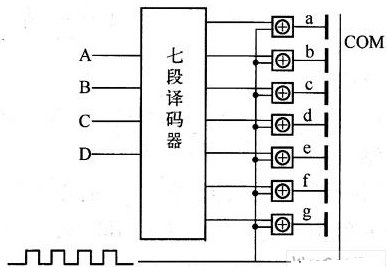
Fig.3 Electrode configuration and static driving circuit diagram of seven-segment LCD
At present, there are many LCD driver integrated chips on the market, and a plurality of LCD driver circuits can be integrated together, which is very convenient to use.
The static driving of the pen section has two characteristics: ① the driving of each electrode is independent of each other and does not affect each other; ② during the display period, the driving voltage is always maintained to make the liquid crystal fully driven. Therefore, compared with the dynamic driving described below, the static driving has the advantages of good contrast, high brightness, fast response, and the like. The disadvantage of static drive is that each pen-shaped electrode requires a control element. When the number of digits displayed is large, the corresponding number of drive elements and leadsTerminalsThe number will be too much, so its application is limited, only suitable for a small number of pen segment electrode display.
Note:
For LCD screens, the following points must be noted:
(1) When driving the liquid crystal display screen, it is not advisable to apply a DC voltage, otherwise, the liquid crystal will produce electrolysis and the electrode will age, thereby greatly reducing the service life of the liquid crystal display screen. Therefore, the liquid crystal display screen must be driven by AC voltage, and the AC component is limited. The DC component is not greater than tens of millivolts.
(2) due to the liquid crystal in the electric fieldOpticsThe change of performance depends on the elastic deformation of liquid crystal as an elastic continuum, and the response time is long, so the effect of alternating driving voltage does not depend on its peak value. Under the condition that the frequency is less than 10 'Hz, the change of liquid crystal light transmittance is only related to the effective value of the applied voltage.
(3) The liquid crystal cell is a capacitive load, and the liquid crystalResistanceIn most cases, it can be ignored and is non-polar, that is, the effect of positive pressure and negative pressure is the same.
Key words:
→ Related news


